Showing posts with label Regulations. Show all posts

Monday, January 22, 2018

CSA Approval Requirements for High Voltage Equipment in Ontario


Canadian Standards Association (CSA) is a non for profit organization accredited for Standard Council of Canada (SCC) to develop Canadian codes and standards. Electrical equipment sold in the market and installed in Ontario shall bear a CSA label which means they have been manufactured and tested according to the relevant CSA standard.
Custom made electrical equipment that are not type tested for mass production, can be factory tested or field tested by CSA, ESA (Electrical Safety Authority in Ontario) or other testing and inspection companies accredited by SCC.
ESA is the electrical safety authority in Ontario responsible for the inspection and approval of all electrical installations in the province.
Conformance with CSA is generally included in the specifications prepared for electrical equipment. However, CSA sticker is not mandatory for high voltage equipment.
For high voltage electrical equipment, the following two provisions are generally included in the specifications in order to meet the code requirements:
1- The high voltage equipment name plate shall include the CSA and/ or other internationally recognized standard the equipment is manufactured and tested to.
2- The control panel(s) shall bear a sticker of an accredited testing facility (CSA or others) to verify the compliance with the applicable CSA standard.

In some cases, the requirement of a CSA blue sticker is added to the purchase order to comply with the second provision above. 
The Blue Sticker indicates that the electric product is tested and meets CSA Group Special Publication SPE-1000. As such, the control panel should have blue sticker otherwise, the product does not meet PO requirement. 

Here is the typical sample of blue sticker affixed on control panel.


CSA Blue sticker is a special inspection label which indicates that the electric, non-healthcare product was tested and has met CSA Group Special Publication SPE-1000, Model Code for the Evaluation of Electrical Equipment, and the Canadian Electrical Code for installations and use. However, the CSA blue sticker is one of the labels that can be used to ensure the control panel meets the relevant code requirements.  


There is a CSA red sticker/ label - shown below- that can also be used for this application. CSA Red sticker is another special inspection label which indicates that the control panel was tested and has met CSA Group Special Publication SPE-1000, Model Code for the Evaluation of Electrical Equipment, and the Canadian Electrical Code for installations and use.


As stated above, there are a number of facilities that can inspect the control panel(s) of high voltage equipment and provide their relevant sticker which would be acceptable by ESA. 

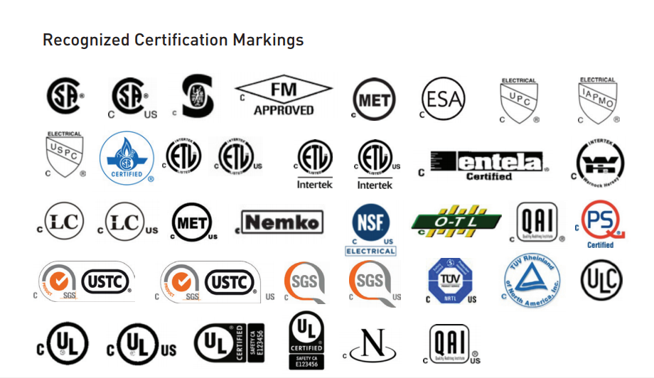
According to ESA product approval card, the recognized certification markings are as follows:


According to the same document the following are the recognized panel-only field evaluation markings:


For example, for any HV transformer installed in Ontario, recognized inspection stickers would be needed for control panel(s) only. As far as the control panel is certified and the transformer nameplate refers to the applicable standards the transformer is built and tested to, the transformer would meet the requirements and will be approved and pass the inspection by the local ESA inspector.


Orange sticker issued by Electrical Safety Authority (ESA), or stickers issued by QPS or Entela depicted above can also be used in lieu of a CSA blue sticker and will be acceptable by local ESA inspector at site.

The certification agencies recognized by ESA are as follows: 


Friday, November 17, 2017

NERC Requirements for Generation Stations


There are number of standards where NERC (North American Electricity Reliability Corporation) dictates specific requirements for the equipment, protection, control and operation of the transmission facilities. The below NERC standards can be referred to for this specific requirement: 
·         NERC PRC 023-2 (Transmission Relay Loadability)
·         NERC FAC-008-3 (Facility Ratings)
·         NERC PRC-025-1 (Generator Relay Loadability)
Although the current industry accepted design based on transmission code -referred to as "Good Utility Practice"- would inherently meet normal NERC requirements, the Engineer shall ensure all the requirements are met since the Client (Generator) would be subject to a NERC audit for compliance after the installation and commissioning of the generation station. 
The Engineer, needs to focus on the design requirements. However, there are more operational requirements that the Generator shall be responsible for and shall be taken into account. In other words, once the Engineer's design meets NERC requirements for reliability, that is where their obligations end.
The existing facilities that do not comply with the latest NERC requirements are allowed to continue to operate. But any major retrofit project or expansion to the existing facilities shall include additional equipment / systems to comply with the new requirements.
Our engineering and design of stations in Ontario -which is based on Ontario Energy Board's Transmission System Code- generally complies with NERC requirements. Two important aspects of generation stations that are mandatory and need to be taken into account during the initial estimate and subsequent design are as follows:    
1- There shall be two battery banks for protection and control equipment. Unlike load stations one common battery bank with two chargers would not be acceptable for generation stations.
2- There shall be a circuit breaker for switching at the switching station. Unlike load stations motorized disconnect switch would not suffice.
Those are the major two features that affect the generation stations. Other NERC requirements shall be similar to those of load stations and would not have a significant impact on the project estimate and the design.
The concern here for generation stations in wind power projects is that while in some cases the generators are derated to suit project requirements, NERC PRC 023-2 and NERC PRC-025-1 require 150% setting on transmission, transformer protection, 130% of rated nameplate of the generator (not de-rated).
This shall be dealt with closely as it could mean that the station and collector system shall be so designed to carry nameplate rated load. This will have a huge impact on the equipment while it can never happen in practice.
In wind generation facilities, loadability is limited by inherent current-limit in WTG's and the cables / transformers will not be overloaded however the relays are generally set to 10%-15% above maximum load per worst case scenario identified in the power flow study and fault overcurrent protections would be based on the fault fed from the grid. If WTG's are derated and the derated MVA has been the base for the design of stepup transformers and the collector cables, then the settings have to be selected for derated equipment loadability again by the power flow study.
The NERC standard has observation to synchronizing generator plants and transmission grid loadability which have 130% generation capability. In wind power projects with Type-4 Generator / Inverters, each generator is able to run up to 105% of its nominal rating then a 130% setting is not effective. If the design is based on /contracted for the derated WTG then the system is registered / recognized to the utility for the derated MVA not nominal generator MVA. Regardless, the generation is limited by generator manufacturer’s setting to the derated MVA.
If the generation is comparable to the grid MVA at the POI (point of interconnection), then the system stability is critical and loadability is important. In most of windfarm projects the source is considered weak-infeed and has no impact on stability then the loadability is more important to the client as profitability!    


Thursday, July 28, 2016

Bare Copper Conductor in Concrete

Bare Copper Conductor in Concrete

Some professionals are reluctant to use bare copper conductor embedded in concrete. They argue that the basic nature of concrete would be a source of corrosion. However this is not a proven argument and different codes and standards have allowed the use of bare copper embedded in concrete as a ground electrode.
The following excerpts of codes can clarify this issue\;

NEC
National electrical code  Article 093, Section E.5 only rules out Aluminum conductor for direct burial in concrete for grounding purposes:

“5. Metals used for grounding, in direct contact with earth, concrete, or masonry, shall have been proven suitable for such exposure.
NOTE 1: Under present technology, aluminum has not generally been proven suitable for such use.
NOTE 2: Metals of different galvanic potentials that are electrically interconnected may require protection against galvanic corrosion.”

NEC article 094, section B.6 specifically refers to copper conductor for use as concrete encased electrode application:

“A metallic wire, rod, or structural shape, meeting Rule 93E5 and encased in concrete, that is not insulated from direct contact with earth, shall constitute an acceptable ground electrode. The concrete depth below grade shall be not less than 300 mm (1 ft), and a depth of 750 mm (2.5 ft) is recommended. Wire shall be no smaller than AWG No. 4 if copper, or 9 mm (3/8 in) diameter or AWG No. 1/0 if steel. It shall be not less than 6.1 m (20 ft) long, and shall remain entirely within the concrete except for the external connection. The conductor should be run as straight as practical.”


CSA
Canadian electrical code Section 10 item 10-700 accepts concrete encased copper conductor as a grounding electrode.

“10-700  Grounding electrodes (see Appendix B)
(3) A field-assembled grounding electrode shall consist of
(a) a bare copper conductor not less than 6 m in length, sized in accordance with Table 43 and encased within the bottom 50 mm of a concrete foundation footing in direct contact with the earth at not less than 600 mm below finished grade”

Also in item 10-806:

“(6) Notwithstanding Subrule (2), a grounding conductor No. 6 AWG or larger shall be permitted to be embedded in concrete provided that the points of emergence are located or guarded so as not to constitute exposure to mechanical damage.”

And in table 43, the size of bare copper conductor is specified for different ampacities of the service conductor:

Table 43
Minimum conductor size for concrete-encased electrodes
(See Rule 10-700.)

Ampacity of largest service conductor or equivalent for multiple conductors, A

Size of bare copper conductor, AWG

165 or less   
4
166–200   
3
201–260   
2
261–355   
0
356–475   
00
Over 475 
000


Saturday, August 29, 2015

Metring Plan


Ontario Transmission Code requires a Metering Service Provider (MSP) to be hired by load or generator customers for metering services. MSPs are third parties certified for the design, installation, commissioning and operation of metering equipment in HV stations.

AS a first step, MSP prepares a metering single line diagram (SLD) and sends to IESO for approval. MSP also prepares a metering plan to be submitted to IESO for approval. However, MSP does not submit the metering plan directly to the IESO as it needs to come from the Metered Market Participant (MMP). The plan needs to be updated with all the information including the MECs.

Once the SLD is approved IESO will then request package 2 to be submitted which will include the EITRP (Emergency IT Restoration Plan) and the MEC documents.  The secondary cable distances between IT's and the metering cabinet is required in order to complete the MEC calculations.

Friday, July 24, 2015

Partial Discharge Test


In terms of interpretation of partial discharge measurements, the results shall be considered acceptable and no further partial discharge tests required under the following conditions:

a) The magnitude of the partial discharge level does not exceed 500 pC during the 1 h test period.
b) The increase in partial discharge levels during the 1 h period does not exceed 150 pC.
c) The partial discharge levels during the 1 h period do not exhibit any steadily rising trend, and no sudden sustained increase in the levels occurs during the last 20 min of the test.

----------------
Reference:

IEEE C57.12.90: Test Code for Liquid-Immersed Distribution, Power, and Regulating

Saturday, February 15, 2014

Oil Containment Dimensions and safe distance between Power Transformers


Oil Containment Dimensions 

and 

safe distance between Power Transformers 


The effective volume of the oil containment shall be greater than or equal to the 110 per cent of the transformer oil. In case the oil containment is filled with gravel, the above percentage shall apply to the available volume of the containment (air pockets) for oil in case of an oil spillage. 

The volume of oil of a specific size transformer, might be different for different manufacturers. The BIL level can also affect the size of the tank and consequently the volume of transformer oil.

For a typical 20 MVA transformer with an Off-load tap changer,  the volume of oil  can be 5000 US Gallons or almost 19000 liters. 

Another important parameter in the design of the containment is the clearance between the transformer and containment wall. According to IEEE recommendation, the minimum horizontal distance of any oil contained part of the transformer and the containment wall would be 1.5 meters. 

Factory Mutual -the prominent insurer of industrial premises- is a good source for safty regulation and clearances and measure to mitigate the risk of hazards in heavy industrial projects including emergency generators, transformers and other station equipment.

Recommendations on the clearances of typical 20 MVA transformer would be as follows:

Between the transformer containment and a combustible wall: 25 feet (7.62 meters)

Between the transformer containment and a 2 hours fire-resistant wall: 15 feet (4.57 meters)

Between two transformers: 25 feet (7.62 meters) 
.
Note 1:  A brick wall is considered to be combustible and do not offer a 2 hours fire resistance.

Note 2: A fire wall would be required to install transformers closer to each other. Minimum distance between the transformer and the fire wall would be 1.5 meters.


Masoud Kashani

February 2014 

IESO Requirements


In Ontario, the protection and control as well as the communication block diagram of any new high voltage substation shall be sent to IESO (Independent Electricity System Operator) for approval. The same applies to the plans for the protection systems upgrades at existing stations.

In case the existing remote trip relays are out of date (say Statrel RT8B ), they shall be replaced with ABB NSD 570 relays and Bell S4T4 (Schedule 4 Type 4) phone circuits. Dual A and B protections for each line shall be provided to communicate with the relays at upstream Hydro One station.

The existing line impedance relay - if out of date - shall be replaced with SEL-421 relays. Reverse power protection may also be required to prevent embedded generation of feeding the grid or back feed of one line by the other in the case of distributed generation stations.

The expected in-service date for the new equipment shall be communicated to the IESO as well.

The IESO shall review the design and onfirm that the proposed upgrades will not result in a material adverse impact on the reliability of the integrated power system.

In any case, the requirements of Transmission System Code issued by Ontario Energy Board shall be satisfied.

February 14th. 2014

Friday, October 5, 2012

Substation Design: Values to report to IESO

In the province of Ontario, prior to the commissioning of any new transmission station, the range of import and export of active and reactive power are key values that are to be communicated with Independent Electricity System Operator (IESO).

For example, in case of a new 115 KV transmission station consisting of a single 20/ 26.6/ 33.2 MVA OA/FA/FA transformer as a load center with the possibility to export  power, the following "Equivalent Engineering Value Range" shall be communicated with IESO:
Active Power: -20 to +40 MW
Reactive Power: -15 to +24 MVAR

The calculation method for active power is as follows:
Transformer capacity is 20/26.7/33.3 MVA. Considering a power factor of unity and 20% overload, then:
Imported Active Power = 33.3*1.20*1 = 40 MW.
The reverse power flow through the transformer is normally considered to be 60% of its capacity. With a unity power factor we will have:
Exported Active Power = 0.6 *33.3*1= 20 MW.

The calculation method for reactive power is as follows:
Transformer capacity is 20/26.7/33.3 MVA. With 20% overload it will reach to 40 MVA. Considering a power factor of 0.8, then:

Imported Reactive Power = 40* SQRT(1- 0.8^2) = 24 MVAR.

On the other hand, the reverse power flow through the transformer is normally considered to be 60% of its capacity. Therefore, 0.6 *33.3 MVA = 20 MVA. The power factor of the 115 kV line is not less than 0.9. Therefore, it shall provide 0.436*20 =8.7 MVA.

The other logic to determine the maximum reactive power flow injected by the facility is when the power flow is towards the facility however, power factor is on the capacitance side. Considering a power factor of 0.9 to 0.95 with 40 MVA can result a reactive power flow of about 15 MVAR. This approach dictates more flow towards the grid. Therefore - 15 MVAR is selected as minimum.


October 2012